Lowpass Filter
The low-pass filter was completely redesigned.
The wired capacitors were no longer available, so I had to
switch to SMD.
To further attenuate the sub-bands of the individual filters, I
switched from a 5th order Chebyshev filter to a 7th order one.
To remain future-proof, the 40 MHz (8m) band and the 70 MHz
(4m) band were also taken into account.
There are now 14 bands available:
160m / 80m / 75m / 60m / 40m / 30m / 20m / 17m / 15m / 12m /
10m / 8m / 6m / 4m
As always, the RX/TX switch is implemented on the low-pass filter and does not need to be implemented separately.
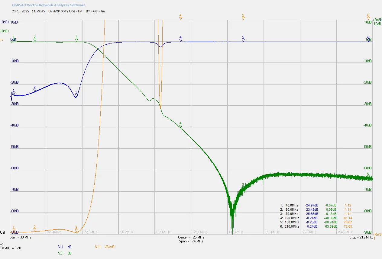
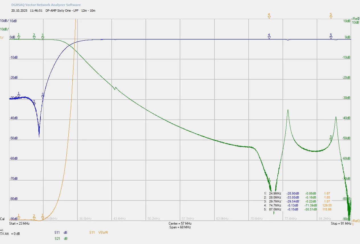
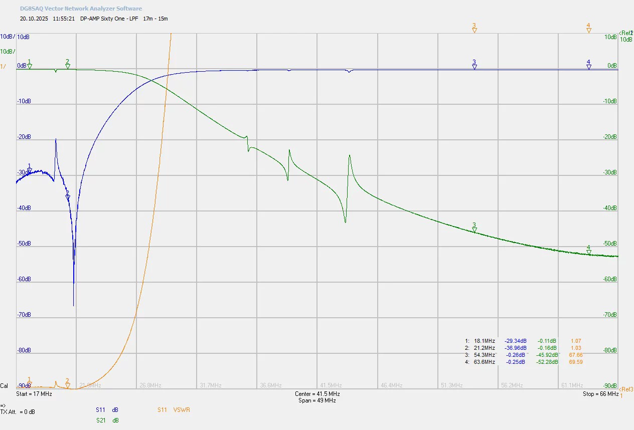
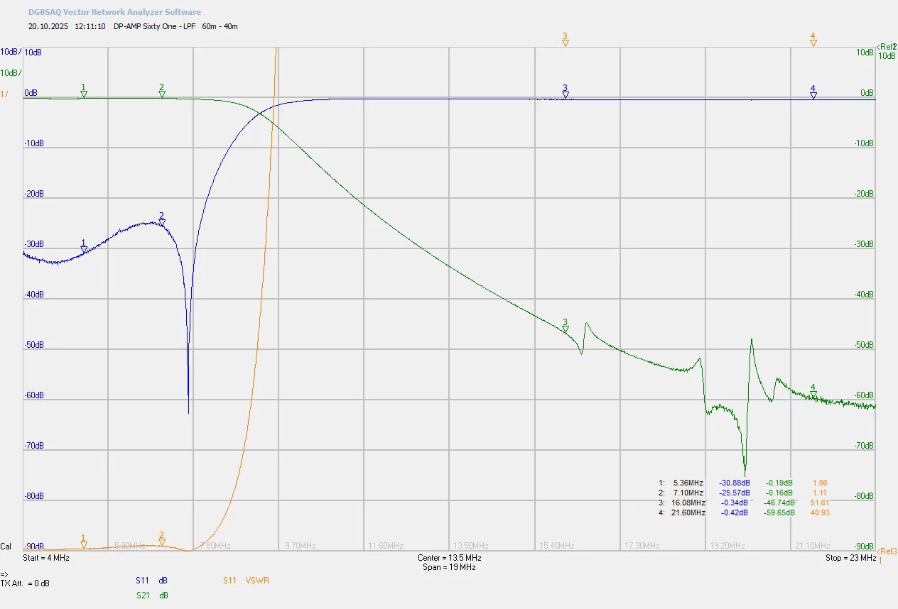
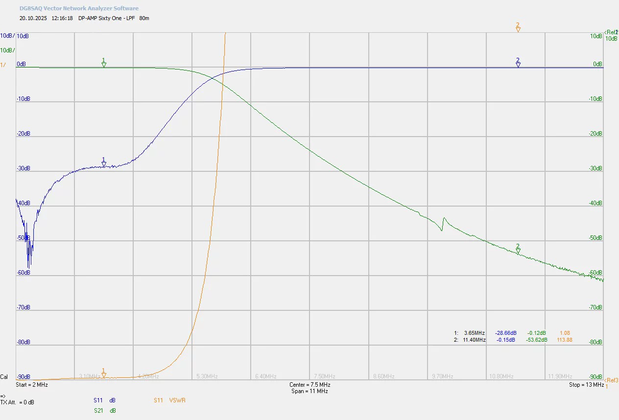
As you can see, the low-pass filter works very well and suppresses the resulting harmonics far better than required by the FCC. The FCC requires -43 dBc, i.e., 43 dB less than the carrier. This is always complied with and the 3rd harmonic is already 10 dB lower at the filter input. So you can read the value and add another 10 dB to get the actual suppression of the 3rd harmonic.
Example: Transmitter 15m, 60 dBm (1000W)
3rd harmonic before the filter 50 dBm (-10 dBc)
Filter attenuation 52.56 dB
Total suppression relative to the carrier (dBc) = - 62.56 dBc
Required by FCC -43 dBc
HF range from 1.7 MHz to 35 MHz -40 dBc
VHF/UHF/SHF range from 50 MHz to 1000 MHz -60 dBc
This means that from a good 50 dBm (100W) of the third harmonic, only -12.56 dBm (0.055 mW) is emitted after the filter.
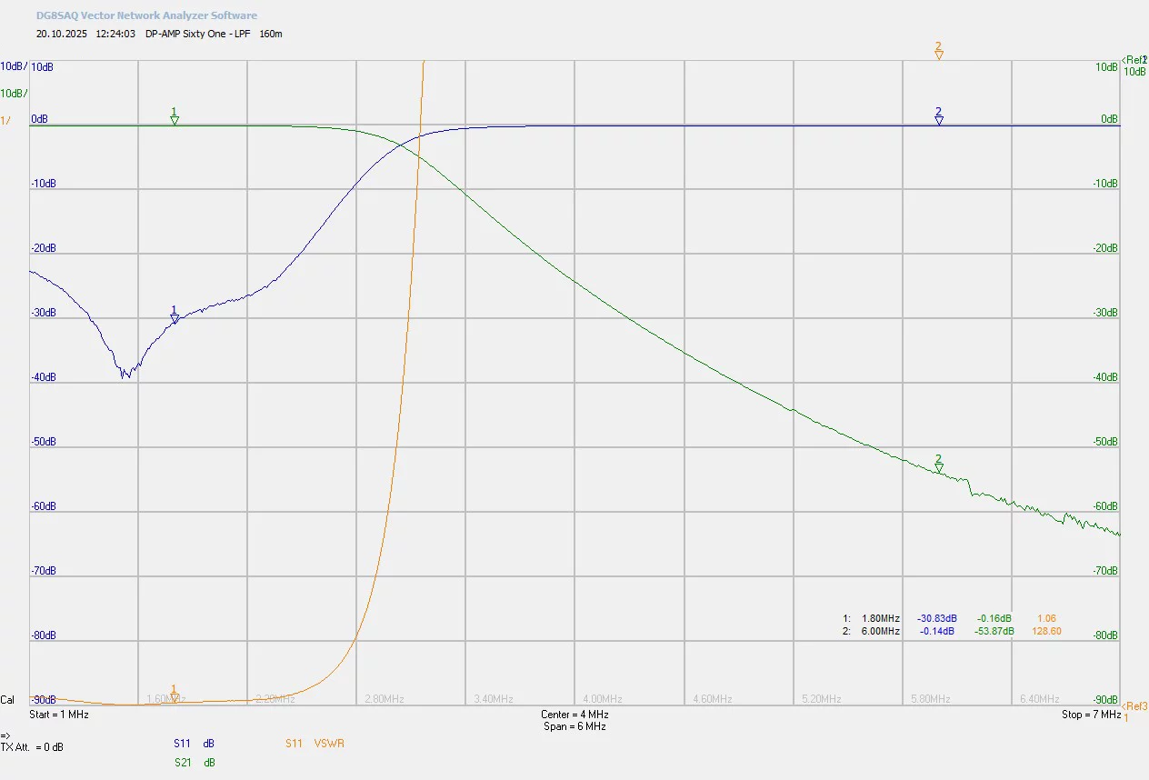
From 50 MHz, the third harmonic must be suppressed by at least
60 dBc.
With a good -71 dBc, this requirement has also been met very
well on 6m and 4m.
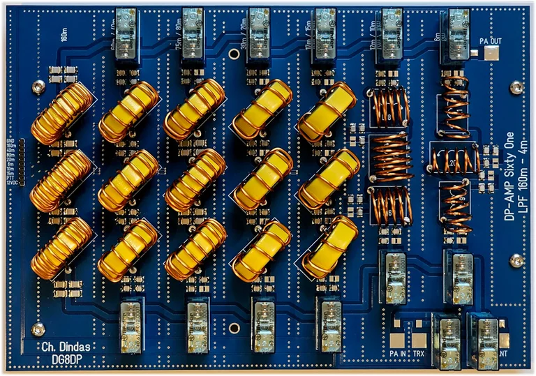
Chebyshev Lowpass Filter 7th order with RX-TX switching